HK4400_B
4x4 4K30 HDMI + USB 3.0 + Audio KVM Seamless Matrix Switcher with Integrated 4-Screen Video Wall Control
Professional 4x4 KVM Matrix for AV and Control Environments
HK4400_B is a professional 4x4 4K30 KVM seamless video matrix designed for meeting rooms, training rooms, classrooms, showroom displays, small control rooms, broadcast support areas and command-center sub-systems. It integrates HDMI video routing, USB 3.0 peripheral switching, audio switching, seamless switching and video wall processing in a compact 1U chassis.
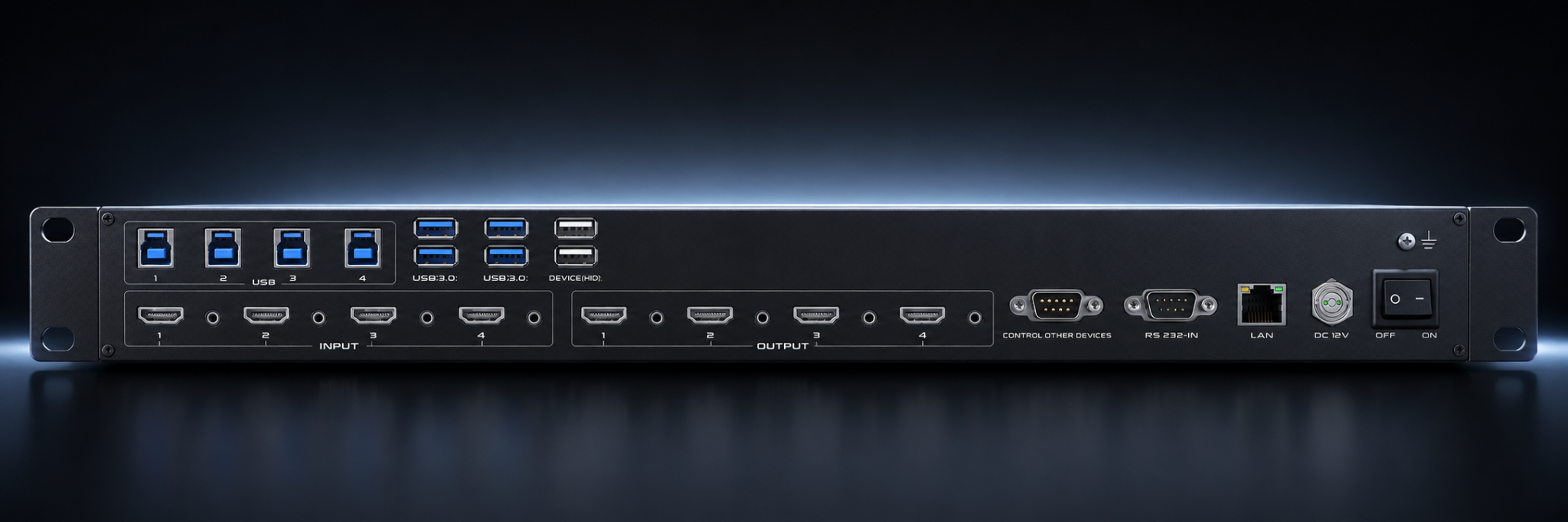
The unit supports 4 HDMI inputs, 4 USB 3.0 host inputs, 4 analog audio inputs, 4 HDMI outputs, 4 USB 3.0 device outputs, 4 analog audio outputs and 2 USB-HID ports for keyboard / mouse and hotkey control. It can be controlled from the front panel, IR remote, HID hotkeys, web interface, RS-232 serial command and TCP/IP network command.
HK4400_B is positioned as a compact professional AV/KVM control core, not a consumer KVM switch. It is suitable for projects that require four-computer switching, USB 3.0 peripheral sharing, audio follow-switching and multi-screen visual presentation.
Operating Mode Definition
Matrix Mode
Remaining Outputs: Dedicated to audio/video (AV) signal routing only.
Video Wall Mode (4-Screen)
Supports USB peripheral switching and sharing across 4 PCs.
The system can combine four displays into a single large image or operate them as independent screens depending on the selected layout and source routing.
Recommended Applications
- Meeting and presentation rooms: Switch between multiple laptops or host computers while maintaining stable image display and shared USB device access.
- Education and training spaces: Route instructor, student, media and camera sources to different screens or to a four-screen video wall.
- Small control rooms: Present dashboards, surveillance, process data and operator workstations on a compact multi-display wall.
- Showrooms and exhibition areas: Use scene recall and seamless switching to present multiple product videos or one large video wall display.
Before Power-On
- Grounding
- Verify that the chassis and system are properly grounded before power-on to reduce electrostatic discharge risk and improve shielding performance.
- Power Source
- Use the supplied power adapter or a qualified power source. Disconnect power before moving the unit or changing system wiring.
- Cable Safety
- Do not place objects on power, signal or communication cables. Avoid stepping on or compressing cables to prevent leakage, short circuits or signal failure.
- Hot Plugging
- Power off the system before inserting or removing signal cables. Damage caused by unsafe hot-plugging may not be covered by warranty.
- Ventilation
- Install the unit in a ventilated, dry and dust-controlled environment. Avoid excessive heat, humidity, liquids and corrosive chemicals.
- Service
- All maintenance should be performed by qualified professionals. Do not disassemble the device without authorization.
Video, USB and Control Features
- Professional 1U Design
- Rack-mount chassis for AV racks, equipment rooms and control cabinets.
- 4K@30Hz Support
- Supports up to 3840x2160@30Hz HDMI input and output.
- Seamless Switching
- Provides fast source switching with reduced black-screen interruption for professional presentation environments.
- USB 3.0 KVM Switching
- Supports USB 3.0 source switching and transparent USB device control for connected PCs.
- Video Wall Processing
- Supports image splicing and four-screen video wall display for compact large-screen applications.
- Audio Follow Switching
- Supports audio embedding at input and audio de-embedding / decoding at output.
- Status Feedback
- Integrated LCD screen provides status display and operation feedback.
- Multiple Control Methods
- Supports front panel, IR remote, web interface, RS-232, TCP/IP LAN, APP and HID hotkey control.
- Scene Memory
- Supports large-capacity scene storage and recall for quick mode switching in daily operation.
System Specifications
- Model
- HK4400_B
- Product Name
- 4x4 4K30 KVM Seamless Video Wall Matrix Switcher
- Input Resolution
- 480p, 576p, 720p, 1080p@24/30/50/60Hz, up to 4K@30Hz
- Output Resolution
- 720p@60Hz, 1080p@60Hz, up to 4K@30Hz
- Input Ports
- 4 x HDMI, 4 x 3.5 mm audio, 4 x USB 3.0
- Output Ports
- 4 x HDMI, 4 x 3.5 mm audio, 4 x USB 3.0, 2 x USB-HID
- Control
- Front-panel buttons, RS-232, LAN, APP, IR remote control and HID hotkeys
- ESD Protection
- Human-body model: +/-8 kV air discharge, +/-4 kV contact discharge
- Power Supply
- AC 100-240V, 50/60Hz input; DC 12V / 3A adapter
- Power Consumption
- Approx. 8.2 W idle; approx. 13 W fully loaded
- Dimensions
- With rack ears: 486(W) x 279(D) x 59(H) mm; without rack ears: 440(W) x 279(D) x 44(H) mm
- Weight
- Net weight approx. 3.42 kg; gross weight approx. 5.42 kg
- Operating Temperature
- 0°C to 50°C
- Storage Temperature
- 0°C to 50°C
Standard Package
| Item | Quantity | Description |
|---|---|---|
| HK4400_B Matrix | 1 | Main 4x4 KVM seamless matrix unit. |
| IR Remote Controller | 1 | Remote operation for switching, menu and scene functions. |
| Mounting Hooks / Rack Ears | 1 set | Rack-mount installation accessory set. |
| 12V / 3A Power Adapter | 1 | Power supply for the matrix. |
| Power Cable | 1 | AC power cable. |
| Ground Wire | 1 | Grounding accessory. |
| User Manual | 1 | Installation and operation guide. |
Front Panel
| Label | Name | Function Description |
|---|---|---|
| A | LCD | Status display and operation feedback. |
| B | INPUT | Input source selection area. |
| C | OUTPUT | Output display selection area. |
| D | CONTROL | UP / DOWN menu navigation, MENU return, ENTER confirmation. |
| E | IR | Infrared receiver for remote control. |

Rear Panel
| Label | Name | Function Description |
|---|---|---|
| F | USB | USB 3.0 signal source input interface. |
| G | USB 3.0 | USB 3.0 device access interface. |
| H | DEVICE HID | Keyboard, mouse and shortcut-key control interface. |
| I | Ground Screw | Chassis grounding point. |
| J | INPUT | HDMI input interface. |
| K | 3.5 mm Audio | Audio embedding input interface. |
| L | OUTPUT | HDMI output interface. |
| M | 3.5 mm Audio | Audio decoding / output interface. |
| N | CONTROL OTHER DEVICES | Control port for external devices. |
| O | RS-232 IN | Third-party control interface. |
| P | LAN | Network control port. |
| Q | DC 12V | 12V / 3A adapter input. |
| R | OFF / ON | Main power switch. |

System Connection Overview
Connect up to four HDMI computers or media sources to the HDMI input ports. Connect USB 3.0 host ports from the computers to the corresponding USB inputs. Connect displays, USB peripherals, keyboard / mouse and speakers according to the required Matrix Mode or Video Wall Mode workflow.

If the external diagram image is not available on the server, use the wiring principles in this section: HDMI, USB 3.0 and audio should follow the same source numbering logic for easier maintenance and operation.
Dimension Reference
- With Rack Ears
- 486(W) x 279(D) x 59(H) mm
- Without Rack Ears
- 440(W) x 279(D) x 44(H) mm
- Installation
- Install in a standard rack, cabinet or stable equipment surface. Keep enough space for ventilation and cable bending radius.
Front Panel Switching
- After power-on, the LCD display remains illuminated and shows the current operating status.
- Press MENU to cycle through pages such as VIEW, SWITCH, SCENE and SETUP.
- For fast switching, press the required input button first, then press the target output button.
- To switch one input to all outputs, select the input and use the shortcut key assigned to all-output switching.
- To cancel a selection, press the selected output again or use the cancel shortcut key.
Scene Save and Recall
The device supports scene storage and recall for fast project operation. After completing the required input/output routing, enter the SCENE interface, select a scene number and press SAVE. To recall a scene, select the scene number and press RECALL.
The system supports a large scene memory capacity. For daily operation, prepare common layouts such as meeting mode, training mode, 2x2 video wall mode and maintenance mode.
Menu Navigation and Switching Mode
Press the MENU button on the remote control to navigate between different menu pages.
To switch signals, press the MENU button on the matrix front panel to enter the SWITCH interface. Use the 4K button on the remote control to switch to Single-Key Mode , or press the 720P button to switch to Dual-Key Mode .
Single-Key Switching Operation
Press the desired input button first, followed by the target output button.
Example: To route Input Channel 1 to Outputs 1, 2 and 3, press Input 1 first, then sequentially press Outputs 1, 2 and 3 . To route Input Channel 2 to Outputs 3 and 4, press Input 2 first, followed by Outputs 3 and 4 .
Dual-Key Switching Operation
Press the input button first, then the output buttons.
Example: To route Input Channel 1 to Outputs 1, 2 and 3, press Input 01 followed by Outputs 01, 02 and 03 .
Ensure the input numbers match your matrix configuration.
Routing Control Keys
| Button | Function |
|---|---|
| UP | After selecting an input, route the signal to all output ports. |
| DOWN | Cancel the current input selection. |
| ENTER | Confirm and map the selected input / output interfaces. |
Scene Saving
Press the MENU button to navigate to the SCENE page. Enter the desired scene number (e.g. 1), then press the SAVE button to store the current switching configuration to that scene.
Scene Recall
Press the MENU button to navigate to the SCENE page. Enter the desired scene number (e.g. 2), then press the RECALL button. Pressing RECALL a second time confirms the action and activates the selected scene.
Web Control Interface
This matrix switcher supports remote control via an intuitive, built-in Web User Interface (Web UI).
- Default IP Address
- 192.168.0.80 via LAN port.
Login Procedure
- Connect your control PC to the same local area network (LAN) subnet as the matrix.
- Launch a standard web browser. Google Chrome is highly recommended for optimal compatibility.
- Enter the device IP address, default 192.168.0.80 , into the browser address bar to open the login page.
- Enter the default system credentials: Username admin ; Password admin .
- Click Login to access the matrix control dashboard.

Video Routing & Switching Operation
Navigate to the top menu bar and select Switch to access the routing interface. The interface is split into the Input Area on the left and the Output Area on the right, with five global control shortcut buttons arranged vertically on the far right panel: Switch All, One Off, All to All, All Off and Save Scene.
- Standard Matrix Routing
- Click the desired source channel button in the left Input Area, then click the target display channel button in the right Output Area. Example: To route Input 2 to Output 4, click 2 on the left side, then click 4 on the right side.
- One-to-Multiple Routing
- Click your designated source channel in the left Input Area, then sequentially click multiple target channel buttons in the right Output Area. Example: To distribute Input 3 to Outputs 1, 2 and 3, click 3 on the left, then click 1, 2 and 3 on the right side in succession.
- Global Video Broadcast
- Select your source channel in the left Input Area, then click the Switch All button on the far right panel to map this single input to all active outputs.
- Disabling a Specific Channel Output
- Click the specific target output port number, then click the One Off button on the far right to disconnect it.
- Symmetrical Mapping
- Click the All to All button to immediately map all inputs to their exact corresponding numerical outputs, such as Input 1 to Output 1 and Input 2 to Output 2.
- Global Output Blackout
- Click the All Off button to instantly disconnect and turn off all matrix input and output routing paths.

Video Wall Layout & Splicing Configuration
Navigate to the splicing section under the Switch menu to configure display array dimensions.
- Creating a New Video Wall Layout
- Locate the grid dimension fields on the top control sub-panel. Enter a custom layout where X represents the column count and Y represents the row count. Click the add button to generate the multi-screen layout grid, such as a 2x2 or 3x3 wall.
- Mapping Outputs to Video Wall Cells
- Select the respective outputs within the matrix interface and assign them to the desired frame cells to match the physical screen deployment on-site.
- Deleting an Existing Layout Profile
- Enter the specific layout or splicing index number in the text field situated directly next to the delete command. Click the del button to clear the selected video wall layout configuration.
Preset Profile & Scene Management
Navigate to the top menu bar and select Scene . The central canvas accommodates up to 10,000 unique presets, managed via the functional controls on the right panel: Save, Load, Rename and Back.
- Saving a Custom Configuration
- First, set up the desired routing states or video wall layouts within the Switch panel. Open the Scene interface, highlight a preset index number from 1 to 10,000, and click the Save button on the right control column to commit the current matrix status to hardware memory.
- Recalling a Stored Configuration
- Highlight the target preset index number from the central grid. Click the Load button on the right control column to instantly deploy the saved routing map.
- Renaming a Scene Profile
- Select the specific scene index number from the grid and click Rename . Type the custom descriptive label into the pop-up text entry window and click Submit to save changes.
- Preset List Navigation
- Click the Back button to instantly jump back up to the top row of the scene management grid.
Centralized Multi-Matrix Management
Navigate to the top menu bar and select Manage to access the centralized cluster control interface.
- Cluster Subnet Capacity
- Users can simultaneously manage up to 254 distinct matrix switcher hosts, provided they reside within the identical local network segment.
- Automatic Device Discovery
- Click the Search button to scan and index active matrix hardware hosts connected online.
- Switching Host Focus
- Click directly on any discovered matrix IP address shown on the top bar to swap the active Web UI control focus to that device.
- Renaming Cluster Hardware Labels
- Highlight the specific device IP address from the cluster list, enter a new alphanumeric tag into the blank text entry field, and click the modification button to apply the changes.
Port Labeling & Customization Operations
Navigate to the top menu bar and select Tag , alternatively listed as Caption . The left workspace displays editable fields categorized into Input Port Names on the top and Output Port Names on the bottom. Use the four alignment buttons on the right to manage the text database.
- Save
- Stores all updated custom port names directly into the matrix onboard hardware flash memory.
- Load
- Syncs data by pulling the currently active port naming profiles from the host back to the web browser.
- Default
- Wipes custom text and restores factory default identifiers, such as reverting labels back to 1 and 2.
- Clear
- Erases all alphanumeric values from the current text customization input blocks.
Serial Command Pass-Through Control
Navigate to the top menu bar and select Control .
- Executing Commands
- Click any of the functional control buttons assigned from 1 to 20 to transmit pre-configured serial commands directly out to connected external peripherals.
- Transmission Delay Control
- A minimum transmission safety gap of one second is strictly enforced between sequential button commands.
Serial Port & Control Command Configuration
Navigate to the top menu bar and select Commands . Click any button configuration slot to toggle the main setup pop-up box.
- Button Customization
- Define specific names for each control macro button; a separate confirmation click is required for every custom entry.
- Command String Formats
- Supports entering strings in either raw ASCII text or hexadecimal HEX formatting.
- Bus Routing & Baud Rate Tuning
- Route command strings through Serial Port 1 (UART1) or Serial Port 2 (UART2) and adjust the specific baud rates to match external hardware specifications.
System Settings & Advanced Configuration
Navigate to the top menu bar and select Setup to handle core system parameters across five separate adjustment areas.
- System Preferences
- Change language, adjust baud rate and perform a soft reboot of the matrix host device.
- Ethernet & Network Configuration
- Enable DHCP to request an IP address from a local DHCP server, or disable DHCP to manually enter static IP address, subnet mask and default gateway values. IP 1 and IP 2 must not occupy identical subnet segments. After changes are filled, click Save Settings , then click Restart Matrix . Network parameters take effect only after a full system reboot.
- User Management Profile
- Modify the administrator dashboard login access security password and click the respective confirmation button to apply the new credentials.
- Input Board Parameters
- Select the specific input board slot and toggle the audio input parameter between extracting Internal Audio or injecting Embedded Audio.
- Output Board Parameters
- Select the desired output channel index path and choose the appropriate output resolution profile from the list. This tool is configuration-only and does not query current display parameters.
- Board Information Display
- Click to force all output cards to project their system OSD information menus on-screen; click again to close them instantly.

Device Information Retrieval
Navigate to the top menu bar, select More , and click Information . Click the sub-panel to view granular hardware metrics, serial IDs and software builds. Firmware and software engineering versions are subject to iterative updates without prior notice.
Firmware Upgrade Procedure
Navigate to the top menu bar, select More , and click Upgrade . Click the file browser to select the authorized upgrade firmware package file, then click to flash and write the update onto the device micro-controller.
Critical safety warning: Firmware flashing carries inherent operational risks. Always verify the file integrity before flashing, and never turn off power or disconnect network connectivity during the process, as doing so may permanently corrupt the device hardware.
Configuration Backup, Import & Export
Navigate to the top menu bar, select More , and click Configure . Select the respective dashboard functions to export current active parameters into a backup file, import a saved profile to deploy settings, or click Clear to wipe custom system configuration maps.
Web Dashboard Theme Customization
Navigate to the top menu bar, select More , and locate the theme configurations. Click Skin Switch to instantly swap the dashboard look between three built-in interface cosmetic styles.
MCS Connect Mobile Application
The matrix switcher supports comprehensive control and configuration via the dedicated mobile application, MCS Connect . Users can download the application according to their mobile platform.
- iOS Users
- Search for "MCS Connect" in the Apple App Store to download and install the application.
- Android Users
- Download and install the application directly from the official website.
Android download link: https://epanio.odoo.com/odoo/documents/h_ZN-DxtRSGhpN52bxumfQo393
Critical Hardware Configuration Required
To ensure proper KVM control and hotkey functionality, the following physical connections must be strictly established on the device rear panel.
- PC Connection
- Connect the host PC to the HOST port using the USB-HOST cable.
- Keyboard Connection
- Connect the control keyboard directly to the USB-DEVICE port.
Hotkey and control operations will completely fail if the keyboard is connected to standard USB peripheral ports, hubs, or unauthorized extenders.
Hotkey Definitions & Command Reference
General Hotkey Execution Rules
| Rule | Description |
|---|---|
| Activation Sequence | All hotkey commands are triggered by pressing the designated prefix key twice consecutively, such as Ctrl then Ctrl or Scroll Lock then Scroll Lock , followed by the specific function command key. |
| Timeout Limit | The complete hotkey sequence must be entered within a strict 3-second window. If the interval between keystrokes exceeds this timeout, the command will expire and the sequence must be restarted. |
| Case Insensitivity | Alphanumeric command keys, such as X, Y or S, are case-insensitive and can be entered in either uppercase or lowercase. |
Direct Input Switching for Output Port 1
Use the double Ctrl prefix for direct signal routing.
| Hotkey Command | Function Description |
|---|---|
| Ctrl + Ctrl + 1 | Switch Input Signal 1 to Output Port 1. |
| Ctrl + Ctrl + 2 | Switch Input Signal 2 to Output Port 1. |
| Ctrl + Ctrl + 3 | Switch Input Signal 3 to Output Port 1. |
| Ctrl + Ctrl + 4 | Switch Input Signal 4 to Output Port 1. |
Scenario Recall for Preset Configurations
Use the double Scroll Lock prefix to call pre-saved matrix scenarios.
| Hotkey Command | Function Description |
|---|---|
| Scroll Lock + Scroll Lock + 1 | Call Scenario 1. |
| Scroll Lock + Scroll Lock + 2 | Call Scenario 2. |
| Scroll Lock + Scroll Lock + 3 | Call Scenario 3. |
| Scroll Lock + Scroll Lock + 4 | Call Scenario 4. |
Connection Specifications
- LAN Connection
- 568B wiring standard
- RS232 Connection
- Direct cable connection
- TCP Port
- 5000
- UDP Port
- 4000
- RS232 Parameters
- Baud rate 115200/200, 8 data bits, 1 stop bit, no parity
Control Command Reference Table
| Command Format | Parameters | Description | Example & Function |
|---|---|---|---|
| YAll. | Y = Input channel number (1, 2, 3, 4...) | Switches specified input to all output channels | 1All. - Switches input 1 to all outputs |
| All1. | None | Sets one-to-one correspondence for all channels | All1. - Maps 1→1, 2→2, 3→3... |
| YXZ. |
Y = Input channel
Z = Output channel |
Switches single input to single output | 1X2. - Switches input 1 to output 2 |
| YXZ&Q&W. |
Y = Input channel
Z, Q, W = Output channels |
Switches single input to multiple outputs | 1X2&3&4. - Switches input 1 to outputs 2, 3, and 4 |
| SaveY. | Y = Scene number (1-10000) | Saves current switching state to memory | Save2. - Saves current state to scene 2 |
| RecallY. | Y = Scene number (1-10000) | Recalls saved switching configuration | Recall2. - Loads scene 2 configuration |
| Beep ON | None | Enables audio feedback (buzzer) | Beep ON - Turns on beep sound |
| Beep OFF | None | Disables audio feedback (buzzer) | Beep OFF - Turns off beep sound |
| Y? | Y = Input channel number | Queries output channels for specified input | 1? - Returns "1x1&2&3" (input 1 routed to outputs 1, 2, 3) |
Command Syntax Notes
- Channel Range
- Y and Z values must correspond to the matrix size (e.g., 1-4 for 4×4 matrix). Invalid channel numbers will be rejected.
- Termination Character
- Every command must end with a period "." (mandatory).
- Case Insensitive
- The "X" separator and all command letters can be uppercase or lowercase.
- Multiple Outputs
- Use "&" symbol to separate multiple output channels in a single command.
Response Codes
| Response Code | Description |
|---|---|
| OK | Command executed successfully |
| ERR | Command execution failed |
Common Troubleshooting
| Issue | Recommended Check |
|---|---|
| No video output | Check HDMI cables, source resolution, output resolution, display power, input/output routing and HDCP compatibility. |
| USB device does not respond | Check USB host connection, USB 3.0 cable quality, selected KVM channel and whether the required mode supports USB switching. |
| No audio | Confirm audio input selection, audio embedding / de-embedding setting, cable connection and amplifier / speaker input source. |
| Cannot access web control | Confirm PC IP is in the same network segment as the matrix, check default IP 192.168.0.80 , network cable and firewall settings. |
| RS-232 control fails | Verify baud rate, data bits, stop bit, parity, cable wiring and command terminator. |
After-Sales Service
If a fault cannot be resolved after basic checks, please contact PANIO sales or technical support. Provide the model name, serial number, firmware version, system wiring description and a clear description of the issue for faster support.