CP1100_B
Wall-Mounted IP Control Host with Volume Knob, Programmable Keys, RS-232, Relay, LAN and PoE
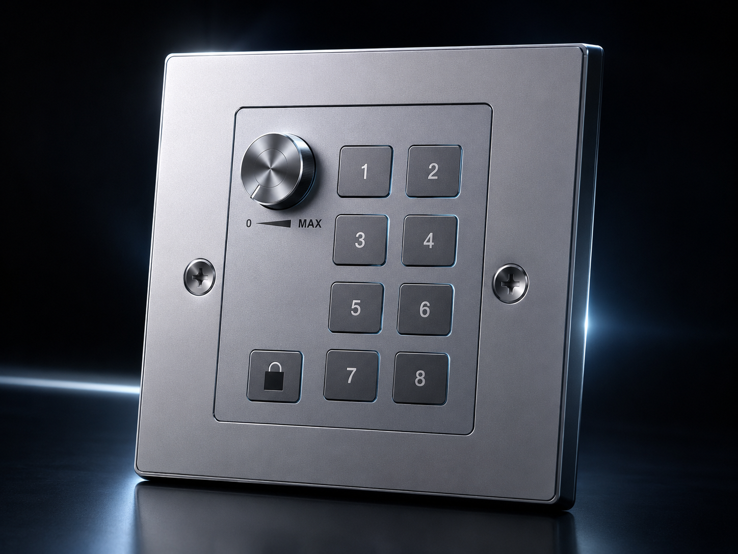
Professional IP-Enabled Control Terminal
CP1100_B is a compact wall-mounted control host designed for professional AV, room automation and centralized equipment control. It provides one rotary volume knob, one lock key and eight programmable silicone command keys for intuitive on-wall operation.
The device supports web-based configuration, allowing system integrators to assign commands to the knob and keys according to the controlled equipment on site. Control output supports LAN command control, dual RS-232 serial ports and dual relay outputs, making CP1100_B suitable for a wide range of project environments.
CP1100_B can be powered by DC 12V or through PoE. When connected to a PoE switch, the product can operate without a separate local power adapter, simplifying cabling for wall-mounted installation.
Before Power-On
- Grounding
- Before powering the system, make sure the chassis and the complete project system are properly grounded to reduce electrostatic discharge risk and improve shielding performance.
- Power Safety
- Use a properly grounded AC power source. Do not remove or damage the grounding pin of the power cable.
- Maintenance
- Before moving, installing or servicing the device, turn off all power sources and unplug the power connector to protect both personnel and equipment.
- Cable Protection
- Do not place heavy objects on power, signal or communication cables. Avoid stepping on, compressing or bending cables excessively.
- Hot Plugging
- Disconnect power before plugging or unplugging signal cables. Damage caused by live connection may not be covered by warranty.
- Environment
- Keep the product away from excessive dust, moisture, liquid splashes, chemical exposure, extremely high temperature or extremely low temperature.
- Ventilation
- Install the device in a stable, well-ventilated location. Avoid heat accumulation inside racks, cabinets or wall boxes.
- Service
- All repair work should be performed by qualified service personnel. Do not attempt internal repair without proper training.
Control and Integration Highlights
- Control Layout
- One rotary volume knob, one lock key and eight programmable command keys for local wall-mounted control.
- PoE Power
- Supports PoE power supply compliant with IEEE 802.3af/at, reducing the need for extra power cabling.
- LAN Control
- One RJ45 LAN interface supports TCP and UDP command control for IP-enabled equipment.
- Serial Control
- Two RS-232 control ports are available for projectors, matrix switchers, processors, displays and other serial-controlled devices.
- Relay Control
- Two relay outputs support latch, release and momentary actions for screen lifts, curtains, power triggers and dry-contact equipment.
- LUA Support
- LUA command entry provides additional flexibility for customized integration logic.
- Web Configuration
- The built-in browser-based platform allows command setup, network settings, account management, firmware upgrade and configuration import/export.
- Panel Lock
- The lock key can disable or enable local and web panel operation to prevent accidental triggering in public or commercial spaces.
Standard Package
| Item | Quantity | Unit |
|---|---|---|
| CP1100_B Wall-Mounted Control Host with Volume Knob | 1 | pc |
| 3-pin Phoenix Terminal Block | 2 | pcs |
| 2-pin Phoenix Terminal Block | 3 | pcs |
| 12V / 1.5A Power Adapter | 1 | pc |
| Power Adapter Conversion Plug | 1 | pc |
| User Manual | 1 | copy |
Check all accessories before installation. If any item is missing or damaged, contact your distributor before commissioning the product.
Device Specifications
- Model
- CP1100_B
- Product Type
- Wall-mounted IP-enabled control host with volume knob and programmable keys.
- Control Interfaces
- Rotary knob, programmable keys, RS-232 ×2, RELAY ×2, LAN ×1.
- Control Protocols
- TCP, UDP, RS-232, relay action and LUA command configuration.
- Power Consumption
- Approx. 4.8W.
- Dimensions
- 86 mm (W) × 86 mm (D) × 39.8 mm (H).
- Net Weight
- Approx. 0.24 kg.
- Package Weight
- Approx. 0.52 kg.
- Operating Humidity
- 10% – 90% RH, non-condensing.
- Operating Temperature
- 0°C – 50°C.
- Storage Temperature
- 0°C – 50°C.
- Power Supply
- Interchangeable plug power adapter, AC 220–240V 50/60Hz input, DC 12V / 1.5A output.
- PoE
- Supports PoE power supply through the LAN port.
Front and Rear Interface Description
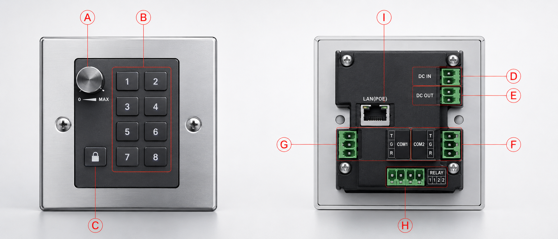
| Mark | Name | Description |
|---|---|---|
| A | Volume Knob | Rotary control knob. Rotate clockwise to increase volume and counterclockwise to decrease volume. |
| B | Command Keys | Press to send configured commands. Eight programmable keys can be assigned for different equipment functions. |
| C | Lock Key | Long press for three seconds to lock or unlock the control panel. |
| D | DC IN | DC 12V / 1.5A power input. |
| E | DC OUT | Power loop-out connector. |
| F | COM2 | RS-232 serial control port 2. |
| G | COM1 | RS-232 serial control port 1. |
| H | RELAY | Two relay outputs for dry-contact control. |
| I | LAN (PoE) | RJ45 network port with PoE support. |
Recommended Network Cable
Use 24 AWG shielded cable with metal conductors and a minimum bandwidth of 400MHz. Shielded RJ45 plugs are recommended at both cable ends.
Web Control Overview
After the CP1100_B is powered on and connected to the network, the built-in web control platform can be accessed through a browser. The web interface is used for daily operation, command triggering, key configuration, network setup, account management, firmware maintenance and interface customization.
The web platform is organized into six main menu items: Home, Panel, Command, Settings, Exit and More. Home and Panel are used for user operation, while Command, Settings and More are mainly used for system configuration and maintenance.
Login Information
- Default IP Address
- 192.168.0.80
- Administrator Account
- admin / admin
- Standard User Account
- user / user
- Access Method
- Open a web browser on a computer connected to the same network segment, enter the default IP address, then log in with the appropriate account.
Before login, set the computer IP address to the same subnet as the CP1100_B. For example, if the controller remains at 192.168.0.80, the computer should use a compatible address in the 192.168.0.x network segment.
Main Menu Structure
| Menu | Primary Function | Operation Description |
|---|---|---|
| Home | Visual command operation | Displays a visual interface for sending configured commands. Except for the rotary knob, the virtual keys on the web page can be clicked to trigger commands. |
| Panel | Virtual panel operation | Provides web-based access to configured knob and key commands, and shows whether the control panel is locked or unlocked. |
| Command | Knob and key command setup | Configures the execution interface and parameters for the rotary knob and eight programmable keys. Supported control types include TCP, UDP, RS-232, relay and LUA. |
| Settings | Network and account setup | Configures static IP parameters, administrator password, standard user password and device reboot. |
| Exit | Logout | Logs out from the current web user session and returns the interface to the login state. |
| More | Maintenance and interface tools | Provides configuration import/export, firmware upgrade, skin switching and language switching. |
Recommended Web Control Workflow
- Power on the CP1100_B through PoE or DC 12V input.
- Connect the computer and CP1100_B to the same network segment.
- Open 192.168.0.80 in a browser and log in with the administrator account.
- Use the Settings page to adjust IP, subnet mask and gateway if required by the project network.
- Use the Command page to configure each knob and key action.
- Use the Home or Panel page to test command triggering.
- Use the More menu to save the configuration file for backup or future deployment.
- Use Exit to log out after commissioning is completed.
Command Page Overview
The Command page is used to configure the operation interface and parameters for the rotary knob and eight programmable keys. Controlled equipment can be connected through LAN, RS-232 or relay output.
IP Control: TCP / UDP
- Name
- Enter the display name for the selected key.
- Protocol
- Select TCP or UDP. UDP settings are configured in the same way as TCP.
- Command
- Enter the command to be sent. ASCII and HEX command formats are supported.
- IP Address
- Enter the IP address of the controlled device.
- Port
- Enter the control port of the controlled device.
Serial Control: RS-232 COM1 / COM2
- Name
- Enter the display name for the selected key.
- Protocol
- Select serial port 1 or serial port 2.
- Command
- Enter the RS-232 command in ASCII or HEX format.
- Baud Rate
- Enter the baud rate required by the controlled device.
- Data Bits
- Set the data bit value according to the controlled device protocol.
- Stop Bits
- Set the stop bit value according to the controlled device protocol.
- Parity
- Set the parity value according to the controlled device protocol.
Relay Control Modes
| Relay Mode | Operation | Typical Use |
|---|---|---|
| Latch | The relay remains closed after the key is pressed. | Power hold, screen up/down control, scene trigger. |
| Release | The relay remains open after the key is pressed. | Cancel trigger, release control, circuit reset. |
| Momentary | The relay closes for two seconds and then releases automatically. | Pulse trigger, projector screen trigger, curtain or dry-contact pulse. |
For relay momentary mode, the relay closes for approximately two seconds and then releases automatically.
LUA Control
Select LUA as the protocol and enter the LUA command in the command field. LUA control is used when the project requires customized logic beyond a standard single command.
Home Page
The Home page provides a visual representation of the control panel. After configuration, keys on the web interface can be clicked to send the corresponding commands. The lock key can also be used to lock or unlock the control panel.
Panel Page
The Panel page allows the user to trigger configured knob and key commands from the browser interface and view the current panel lock status.
Lock / Unlock Operation
- Lock / Unlock Method
- Long press the lock key for three seconds.
- Lock Indication
- After holding the lock key, all key indicators flash three times to confirm the lock or unlock action.
- Locked State
- When the panel is locked, keys are displayed in a disabled / light-gray state. Physical keys and web keys do not send commands.
- Unlocked State
- When unlocked, the physical panel and web panel can trigger configured commands normally.
Use the lock function in public spaces, classrooms, exhibition areas and commercial sites to prevent unintended operation.
Network Settings
- IP Address
- Enter the static IP address of CP1100_B.
- Subnet Mask
- Enter the subnet mask for the project network.
- Gateway
- Enter the gateway address for routing if required.
- MAC Address
- The physical MAC address is displayed for reference and is not open for editing.
Account Settings
- Administrator Username
- Default administrator username is admin and cannot be changed.
- Administrator Password
- Enter and confirm the new administrator password.
- User Username
- Default standard username is user and cannot be changed.
- User Password
- Enter and confirm the new standard user password.
More Menu Operations
| Function | Description | Important Note |
|---|---|---|
| Configuration Upload | Select or drag a configuration file into the upload area, then upload it to update key names and commands. | Do not manually edit the configuration file; otherwise the controller may fail to recognize it. |
| Save Configuration | Exports the current key names and command settings as a configuration file. | Recommended before firmware upgrade or batch deployment. |
| Restore Factory Configuration | Clears configured names and commands and restores the default configuration. | Use with caution; existing command settings will be removed. |
| Firmware Upgrade | Select or drag the upgrade file into the upload area, then start the upgrade process. | Backup the configuration before upgrading. Do not power off during the upgrade. |
| Skin Switching | Switches the web interface between dark and light skins. | Select interface style according to project preference. |
| Language Switching | Switches the web interface language. | Useful for international projects and bilingual commissioning. |
| Reboot | Restarts CP1100_B immediately after confirmation. | Ensure current settings are saved prior to rebooting. |
Typical Deployment
CP1100_B is designed for multi-device control in professional environments. It can be mounted on a wall and connected to the project network through LAN/PoE, while RS-232 and relay outputs connect directly to AV devices or dry-contact equipment.
Common Issue: Cannot Connect to the Controller
| Check Item | Action |
|---|---|
| IP Address | Confirm that the browser is accessing the correct controller IP address (192.168.0.80 by default). |
| Computer Network Segment | Make sure the computer IP address is configured in the same network segment as CP1100_B (e.g. 192.168.0.100). |
| Network Cable | Check whether the network cable is damaged, bent excessively, or disconnected. |
| RJ45 Connector | Check whether the cable wiring and RJ45 connector shielding are intact. |
| PoE Switch | If using PoE, confirm that the switch supports IEEE 802.3af/at PoE power output and that the port is enabled. |
Warranty and Service Notice
Under normal use and in accordance with official service support requirements, the product is covered against workmanship and material defects for one year from the date of purchase from PANIO or an authorized distributor.
Warranty service may include repair, replacement with an equivalent product or component, or refund according to the service policy. The warranty does not cover damage caused by misuse, incorrect operation, negligence, accident, abnormal physical stress, abnormal voltage, unauthorized modification, or service performed by unauthorized third parties.
Before sending the product for service, back up any configuration information where possible. PANIO is not responsible for software, firmware, information or stored data contained in products returned for repair.